
Moasure is a site measurement technology company, new to the design and construction industry. It offers a state of the art accelerometer based measurement toolkit, differentiated from establised survey technology such as theodolites, transits or laser scanners, many of which are expensive investments and often require more than one operator on site as well as significant offsite post-processing. Moasure’s toolkit, which balances capture speed and accuracy with fitness of purpose of layout, area and volume calculation, also offers a reporting application for mobile devices which automates many of these calculations to provide results and deliverables near real-time. These deliverables include Cut and Fill reports, surface based material volume calculations, contour and 3d height graphics.
Though we exist in the age of digital disruption driven by the provision of technology such as Moasure, a degree of human skill and mastery is still required to get the most out of the technology to hand. This post intends to explain how to leverage Moasure One and Two technology to capture and create outputs which could have higher reliability than that which is provided by Moasure’s core algorithms and reports.
This post is divided into two areas. The first is a description of advanced site behaviours and processes, inspired by traditional survey methods but adapted to Moasure. The second is the use of digital processing concepts which may be employed as recipes using exported CAD formats and are performed on desktop or laptop computer.
Site behaviours
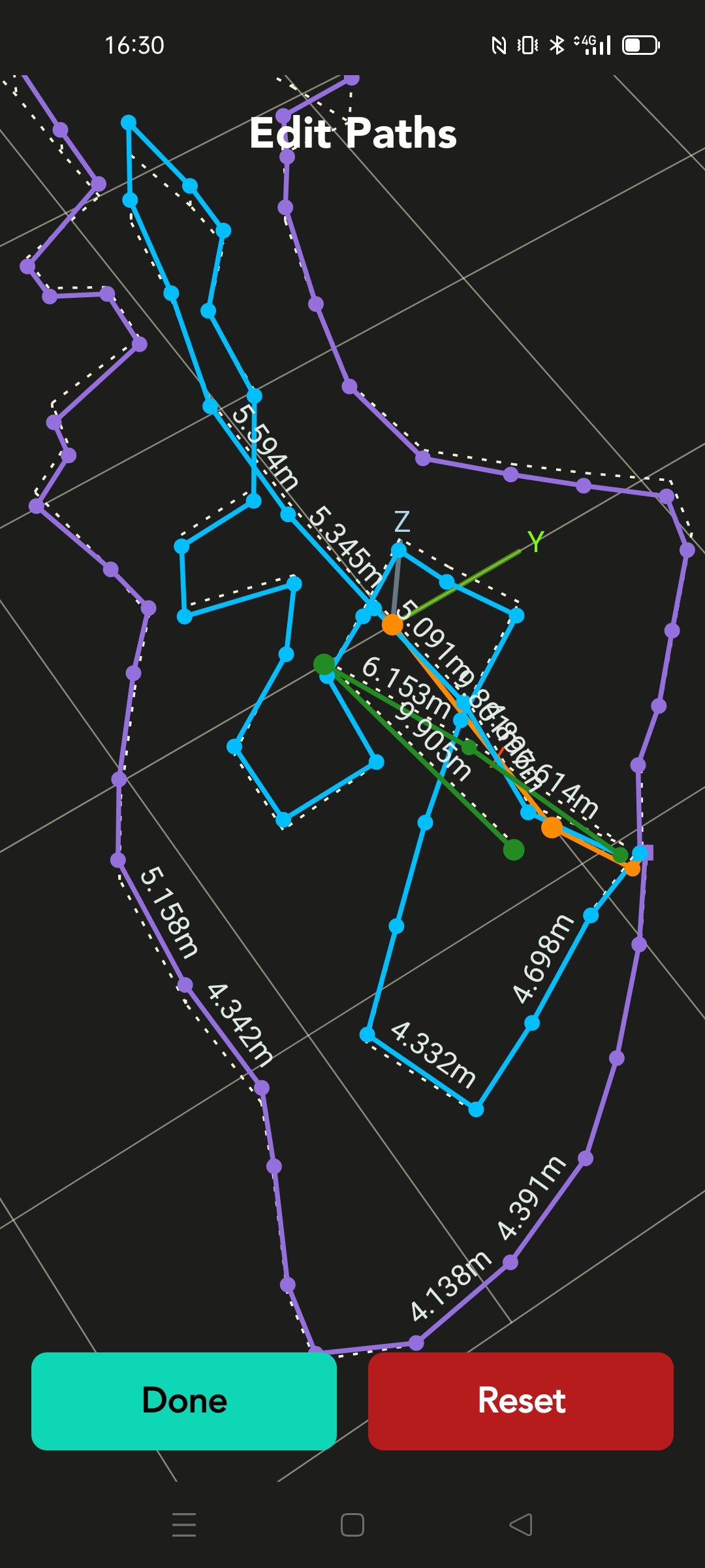
1. Starting, switching line types, finishing and annotating a measurement (with a view to self-diagnosing inaccuracy)
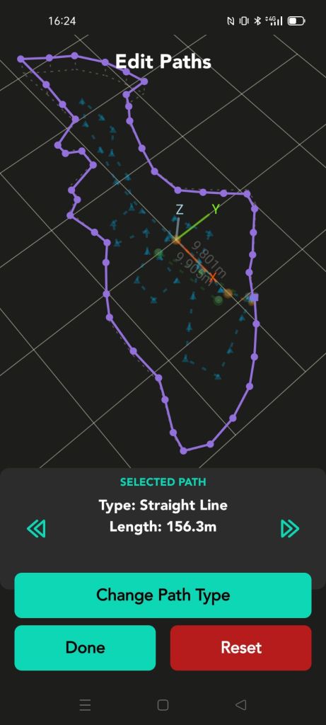
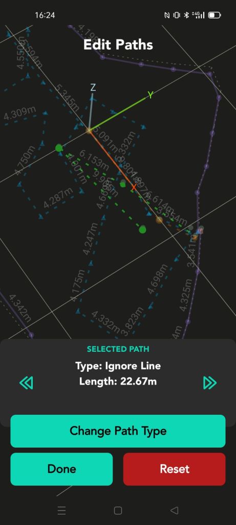
This series of images aims to explain the sequence of capture and ‘switches’ between line types to ensure that checking is enabled after the capture process. Desktop processing is possible, outlined in later steps, if site time is limited. Good results are still possible with less desirable topographical capture steps, similar to that shown above.
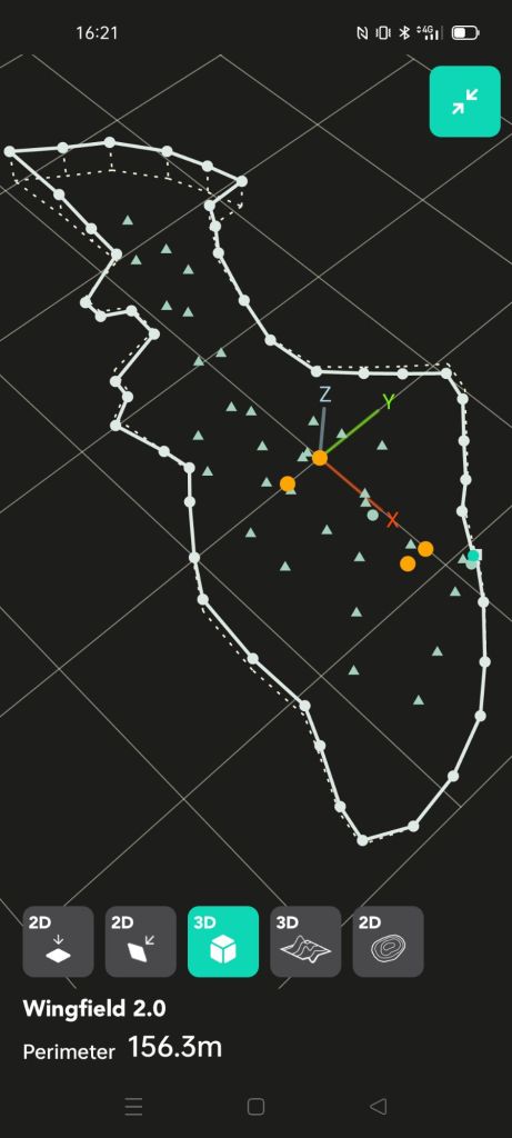
2. The use of Datum edges and triangulation using a ‘primary infrastructure’

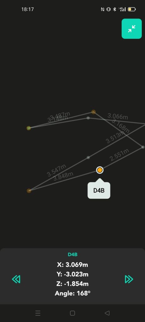
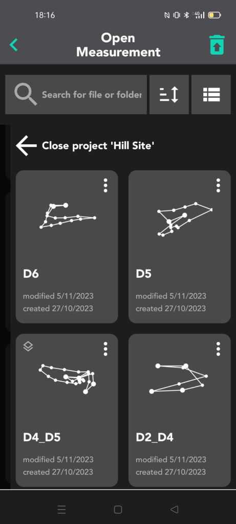
This series of images and video intends to explain the creation of multiple separate files according to an abstract methodology of triangulation of a series of connected datum edges. This essentially forms a connection scaffold to which other files may be referenced, and attempts to keep accuracy high by staying close to the centre of each model or breaking larger or challenging sites into manageable chunks.
This methodology comes with the tradeoff of only being able to create visualisation in a desktop environment, forgoing the ability to use Moasure’s more automated report generation. The usecase, therefore, is that of eliminating the requirement for expensive laser scanning or traditional totalstation survey requiring more than one person and with time consuming station setup and obscured reflector sight paths. Moasure can operate on challenging hill sites for the purposes of moderate accuracy contour capture, Enabling concept site designs, construction planning and works monitoring.
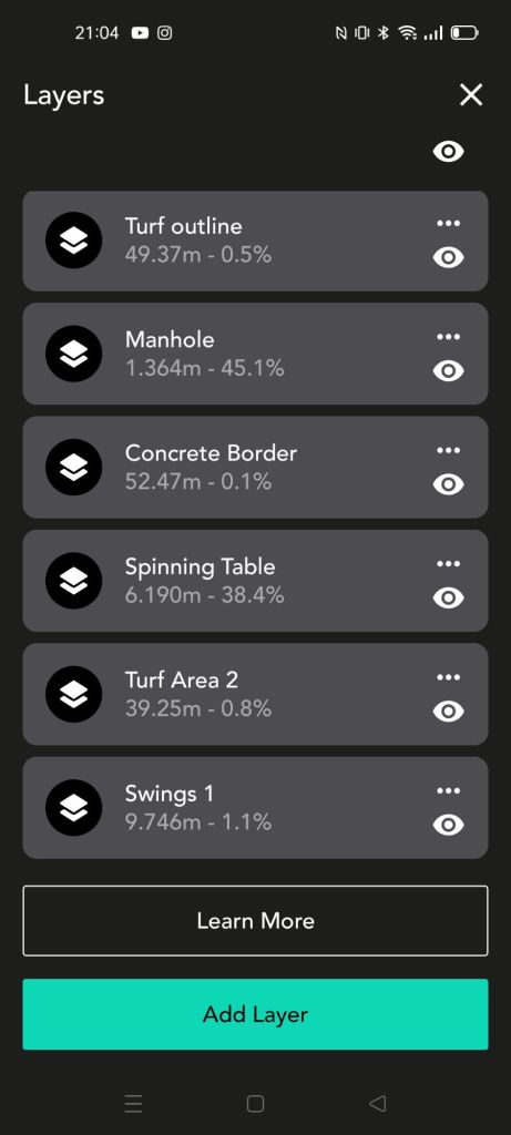
3. The use of layers to incrementally build site data sets
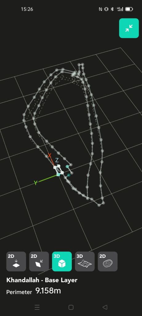
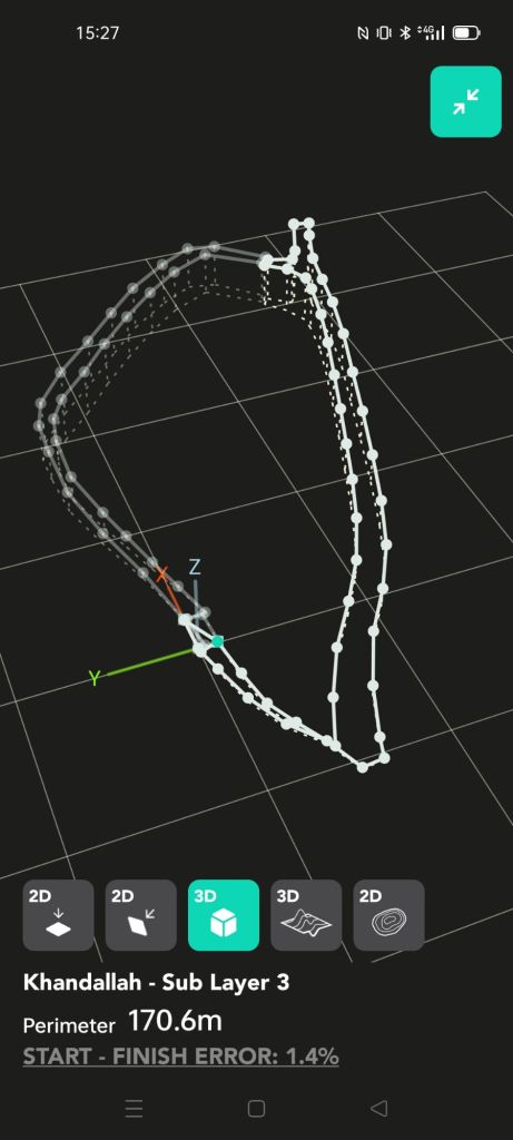
With layering functionality, sites can be built gradually, with maximum control over quality. Numerous ‘takes’ can be made for each feature, meaning if known error is induced (e.g. too many points taken in the ‘orange’ or ‘red’, or conspicuous strangeness in comparison), data can be corrected almost real-time on site. Some rules of thumb follow below;
- Start with the base layer starting edge central to the site. This means that error is reduced when traversing to the site corners.
- Re-take the base layer with one or two overlay layers to check its integrity. Delete the check layers.
- Use invisible edges to traverse to the starting straight/solid edge, and close the straight/solid measurement against its own start point. Traverse back to the layer start edge using invisible lines to check the relative rotational error. If too much is incurred, re-measure the feature using a new layer.

Processing with computers (in this case using Blender3D)
1. Preparing exports and Import into Blender
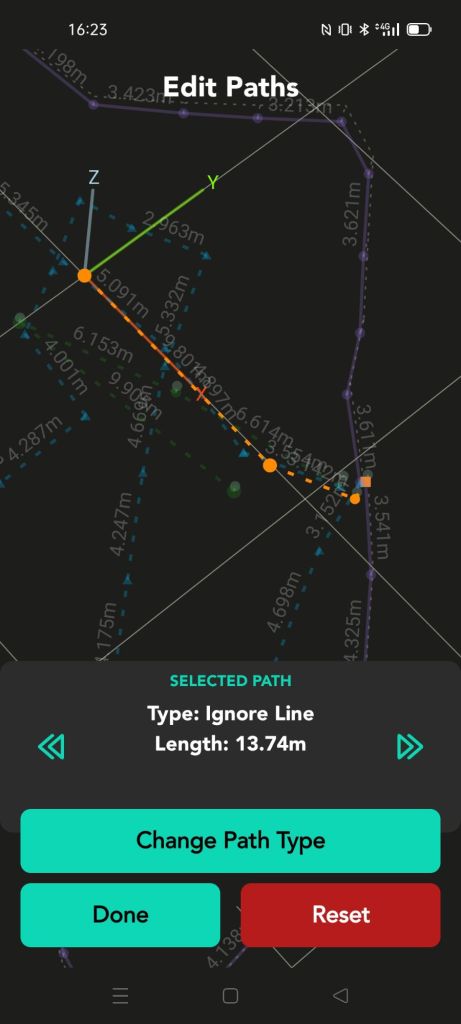
The use of export to DXF is proposed in this process, which also includes the conversion of all lines within the Moasure app to solid/straight. In addition, all measurements should be ‘open’ in order to correct the measurement in windows computer applications (next section).


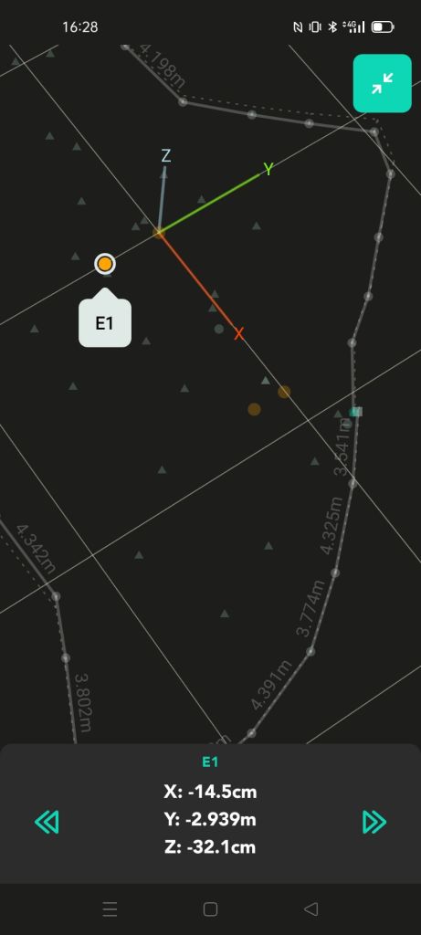
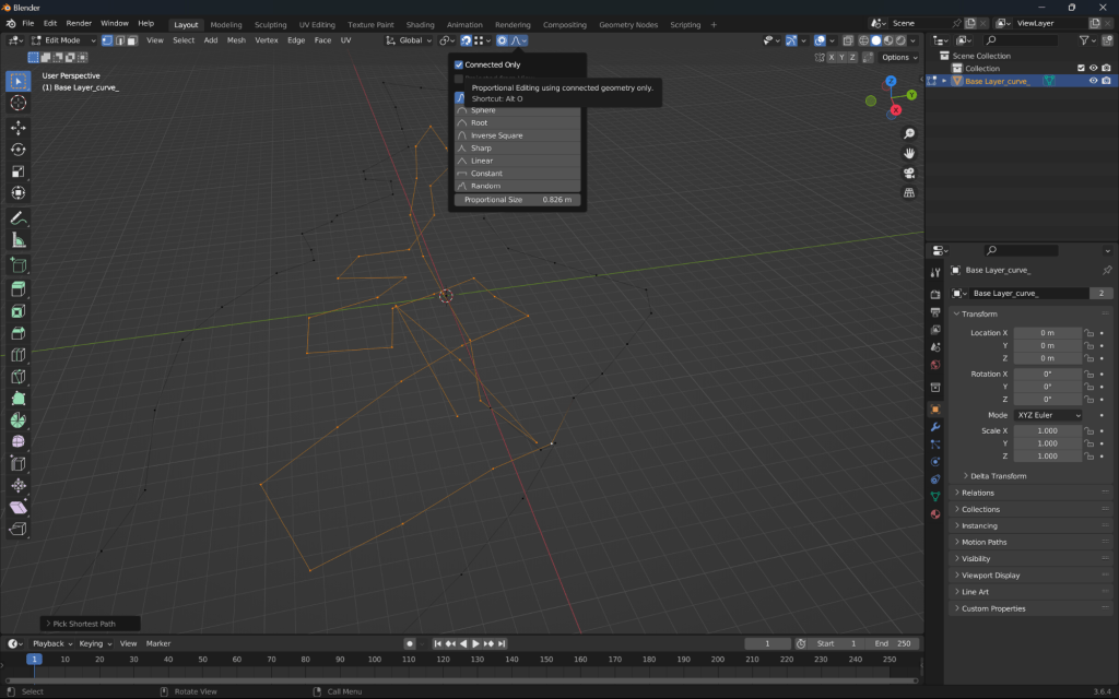
2. Checking and correction of paths for translational and aggregated rotational error (ARE)
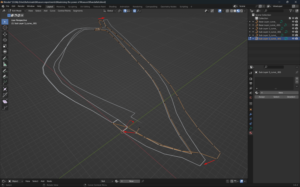
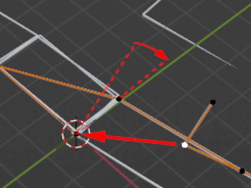

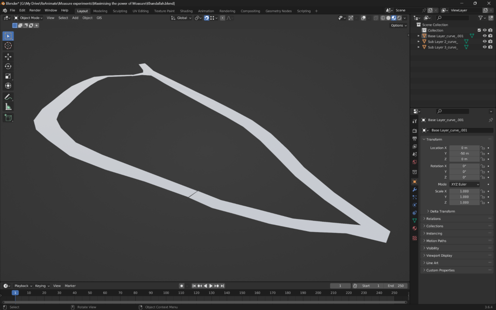
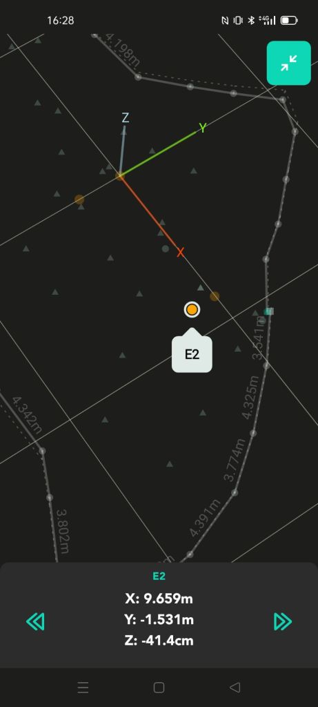
With this series of images I propose that both translation and rotation error should be corrected after import into a secondary mesh editing tool, in this case, Blender3D. Moasure’s closure algorithm appears to only translate end to the start point, hence misses the opportunity to correct for ARE. Using the concept of ‘soft selection’, the user can select on the end edges of the measurement and gradually affect a correction through the network of connected edges backwards towards the start points. In short, there is greatest correction at the end of the measurement and minimal correction at the start, in BOTH the translation (x and y) as well as rotation (around the z axis).
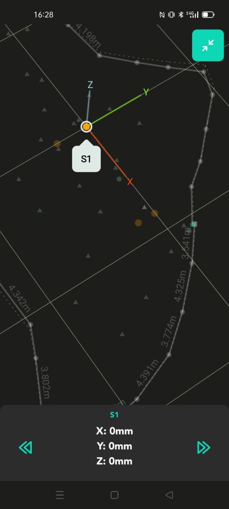
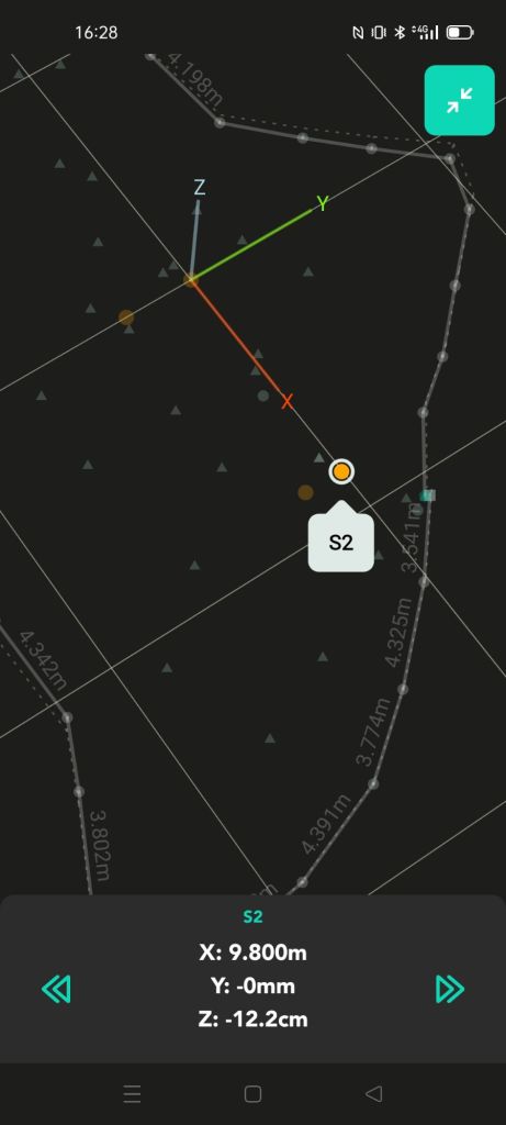
This correction is enabled through the capture of the reference edge at the end of the measurement (identical points as the start and second points of the measurement) providing conspicuous comparision between the original edge and the final edge representing the ARE.
Additionally, If the measurement was captured using rotations of the device in one direction only (for example always clockwise), one may assume that this will help with correcting ARE and have more accurate control over the measurement in general, affecting all zones of the measurement with maximum consistency.
3. Triangulation of surface data using GIS and/or Delaunay technique ( & bringing it all together)
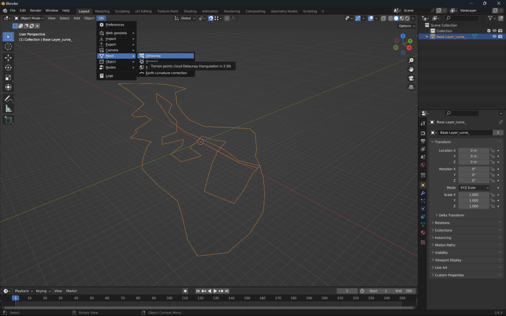
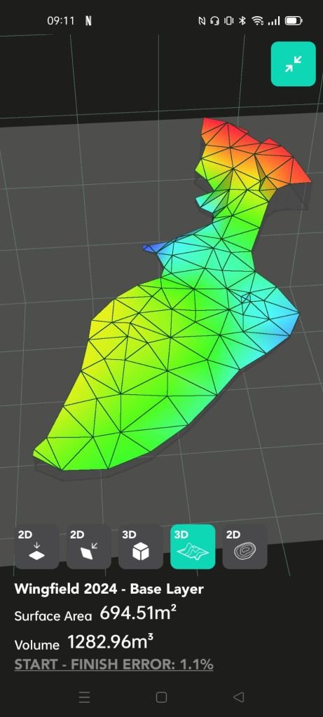
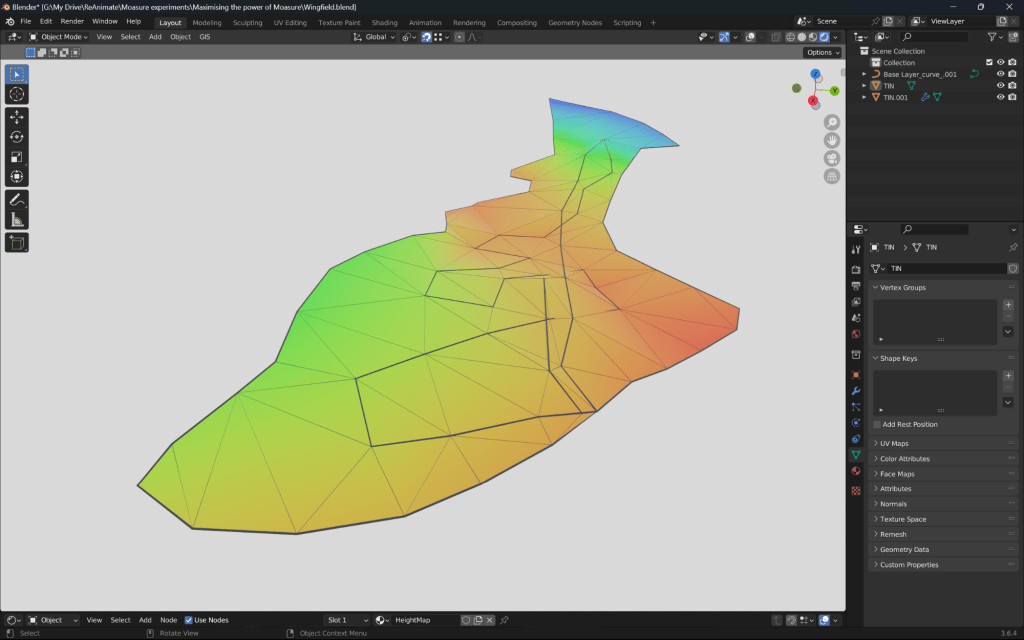
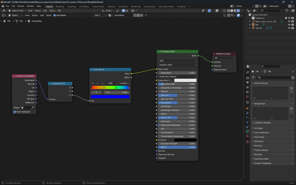
Using Blender3D, the surface is triangulated using the plugin BlenderGIS. Following earlier correction steps, the surface can be reproduced for additional use such as animation and visualisation. An image of the heightmap material is also included to show the customisation possible using visualisation tools with Moasure data such as Blender3D.
Moasure improvement suggestions
Moasure is an excellent and disruptive tool. The device itself is excellent and has clear reliance on its supporting mobile application and user techniques as outlined above. Therefore, these suggestions are centred on making the application prompt the user for the best possible outcome. Software and methodology recommendations are as follows;
- The ability to create toposurface measurements through the use of layer combinations rather than a continuous measurement that changes type (the current workflows), ensuring both boundary and spot heights (point measurement) are as high quality as possible. The current workflow incurs too much aggregated translational and rotational error at present.
- Prompting or allowing the user to correct for aggregated rotational error (ARE) through the capture of a final comparative edge at the end of each measurement (similar to the above), which is automatically or optionally applied like the auto-join functionality. Moasure’s ‘join’ algorithm may then also require an update to its mathematics to perform a rotational correction similar to the soft selection method explained earlier.
- The ability to export a csv or similar record of the capture time between each sample point in measurement, additionally, if possible, with a record of the ranges of gyroscopic deviation (violence or smoothness of the movement between sample points). This would allow custom scripting to determine zones of high versus low reliability in the measurement during desktop correction steps. This concept could also be considered for moasure application algorithms if not already included.
Conclusion
This post aims to summarise the best techniques in the use of Moasure One and Two technology that I have found to ensure onsite and offsite measurement quality is retained. A key finding is that the concept of ARE (aggregated rotational error) has some impact on measurement quality but can be mitigated using capture and processing techniques using import/export into secondary computer tools.
I welcome questions and discussion about this disruptive and exciting technology. Contact me here, or find and message me on my various social media accounts.
