

The following post explains the significant steps taken in a typical small to medium reverse engineering project, using a hundred-year old door locking mechanism as a subject. This post will be divided into 5 steps. First, a video explanation of the tools and process that the studio features.
Studio layout and technology required
The requirements are relatively simple – not much is needed. We have the basics:
- A1: surface plate, which is validated to be within 0.02mm planar deviation. This ensures readouts for vertical offsets are of an acceptable accuracy.
- A2: A height gauge (Vernier). Also to 0.02mm graduations. This allows wider plates/pressed regions can be measured for depth, when jaws of hand held calipers aren’t long enough.
- A3 and A4: Vernier calipers, to 0.02mm. These may be analogue or digital. I prefer analogues as I have had unrealizabilities with digital calipers in the past, and they also recalibration through time. While analogue scales may be less ‘legible’, checking processes ensure that these readings are validated numerous times.
- A5 – A7: Radius gauges from 1mm -25mm. Most small to medium parts are covered here by this range. These are effectively rounded metal plates/leaves, which can be held up to the parts to determine the size of filleted corners and edges.
- A8: Metric and Imperial thread gauges. Measured in pitch (metric) or turns per inch (imperial). Combined with Vernier calipers to determine diameters, most threads can be identified.
- A9: Engineer’s black book. This features a vast amount of tables for drill sizes, angles, tolerances, and thread tables. This is an absolutely critical bit of equipment for any machining or reverse engineering shop.
- A10 (not shown): Hand-held 3d scanner. I use an XBox360 Kinect sensor, or a photogrammetry process for anything that needs recording before being disassembled or has compound surfaces or levels of complexity beyond measurement with the tools listed above.
What don’t we have, that we will be investing in, or could be utilized in a third party workshop?
- Long-Jaw Vernier calipers, for larger engine components – 300mm to more than one metre in scale length. This item will be invested in, as and when required.
- Hardness tester for critical or heat treated components. I have had mixed success with desktop hardness testers. This test would likely be outsourced to specialist machine shops if required.
- ‘Micro’ measurement gauges such as micrometers, dial indicators & cylindrical deviation. A workshop with a CNC mill would be utilized for critical cylindrical faces such as crankshafts.
- Material composition reporting for critical components. This would be outsourced to another laboratory.
The process
What are the significant steps and treatments involved?
1. Inwards goods and entry into the workflow
The first treatment is the receipt of the part or assembly that needs work. In our systems, the incoming part or assembly receives an internal job number and sheet, which has the range of processes that could be required, such as disassembly with different approaches – simple mechanical disassembly, heating, acid bathing, or other means. Other parts of this job sheet enable the recording of time, part replacement information and digitization subprocesses such as methods of measurement, model-based or drawing-based documentation.
2. Disassembly and cleaning
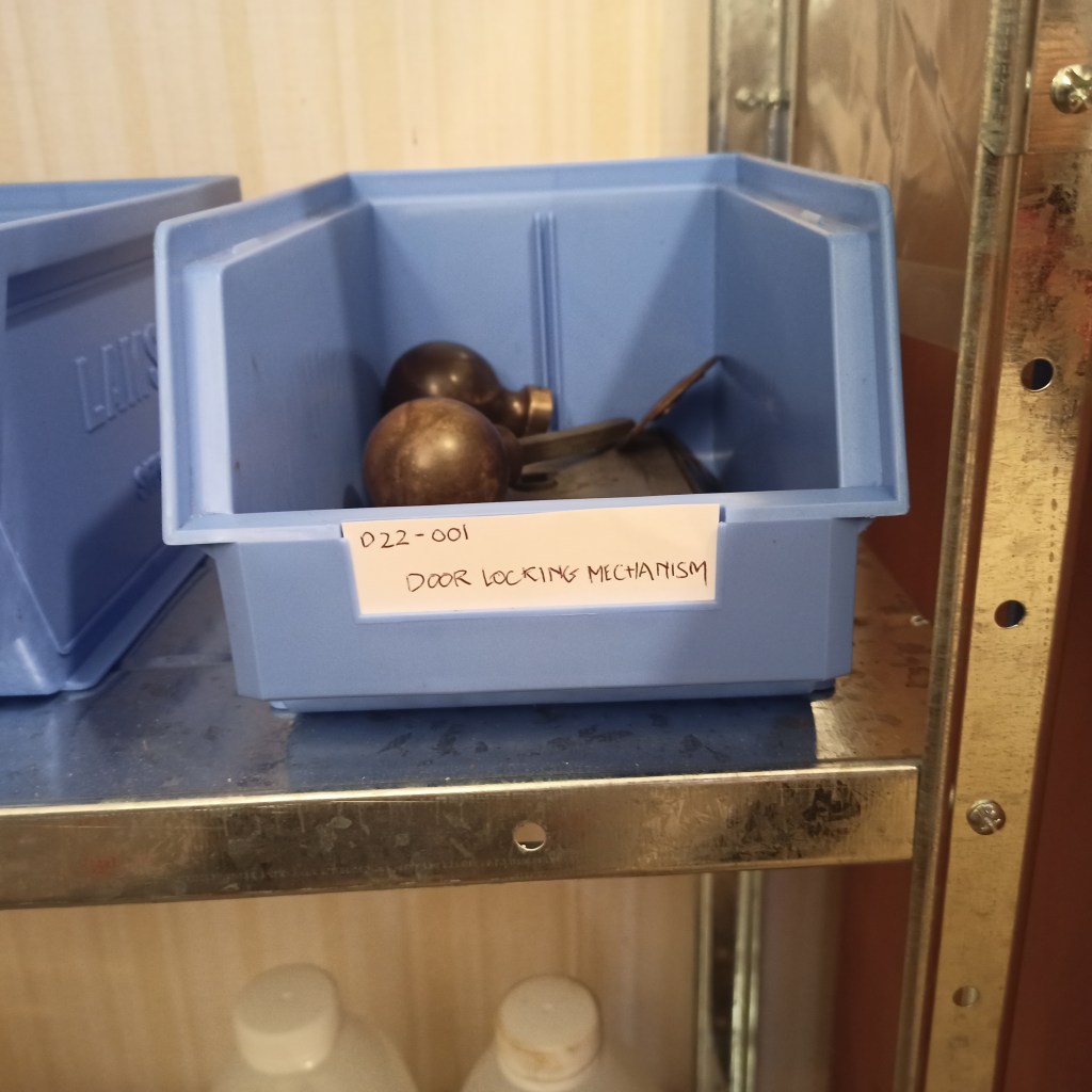
These steps generally go hand-in-hand for assemblies. For small and medium ones, rigor is exercised with tracking parts through different cleaning processes. Labelled trays keep assemblies together, as well as digital tape labelling for temporary containers for soaking, electrolysis or more significant work with parts washing machines. Some material and finish recording takes place at this point and recorded on physical job sheets and digital datasheets, and further decisions are able to be made such as heating, rust removal method or blasting, if heat treatments or surface finishes need to be retained. Once disassembly has occured, the parts may be sent to priming, painting or plating, or simply stored ‘sealed’ with rust preventative spray as shown.
3. Digitization
As described earlier in this writing, we have a collection of tools in-house which represent what is needed for approximately 95% of the parts in a typical mechanical assembly. The main tools are the vernier caliper, thread and radius gauges, and the Engineer’s Black Book, which enables the identification of thread types, hole sizes, fits and tolerances.
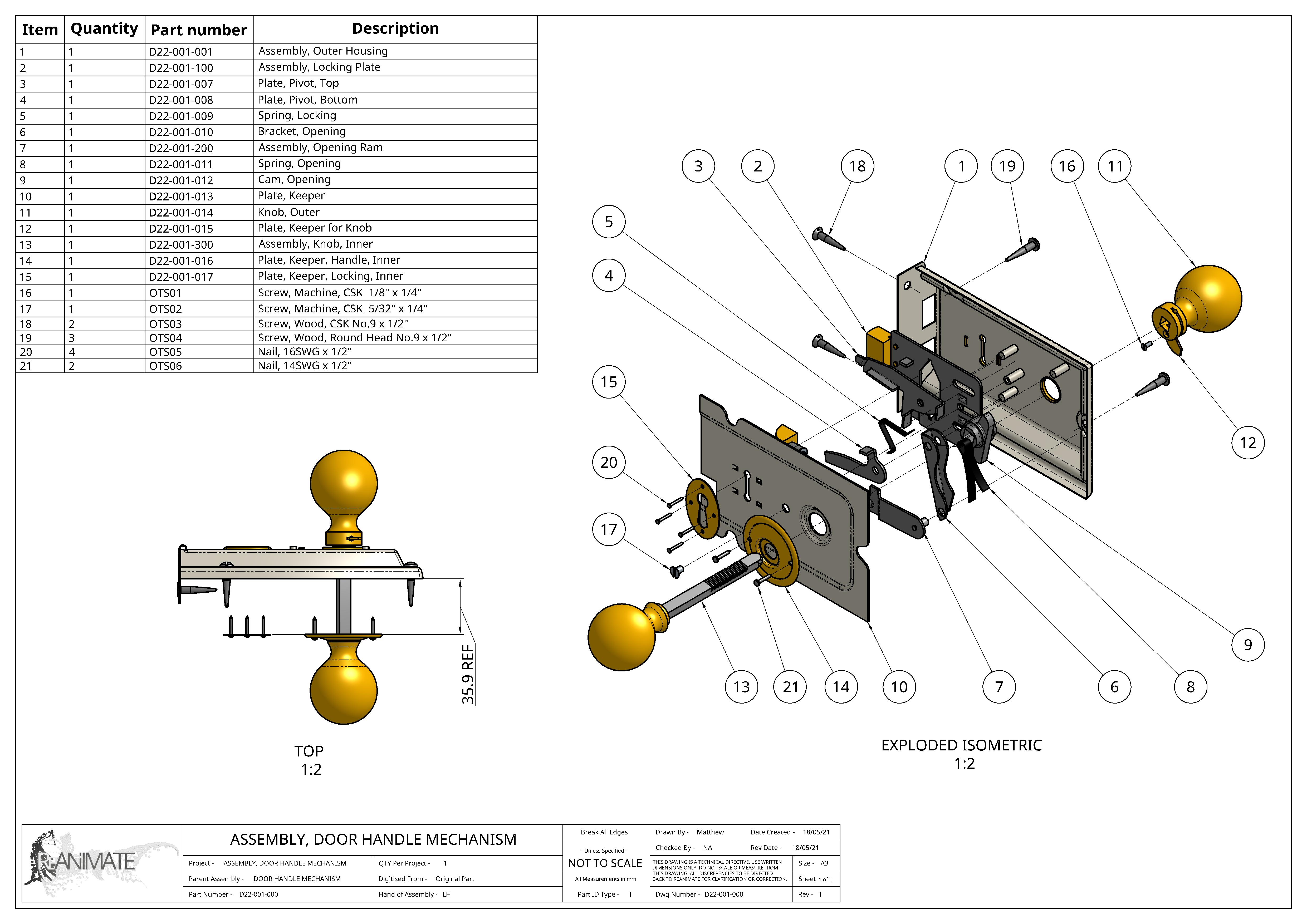
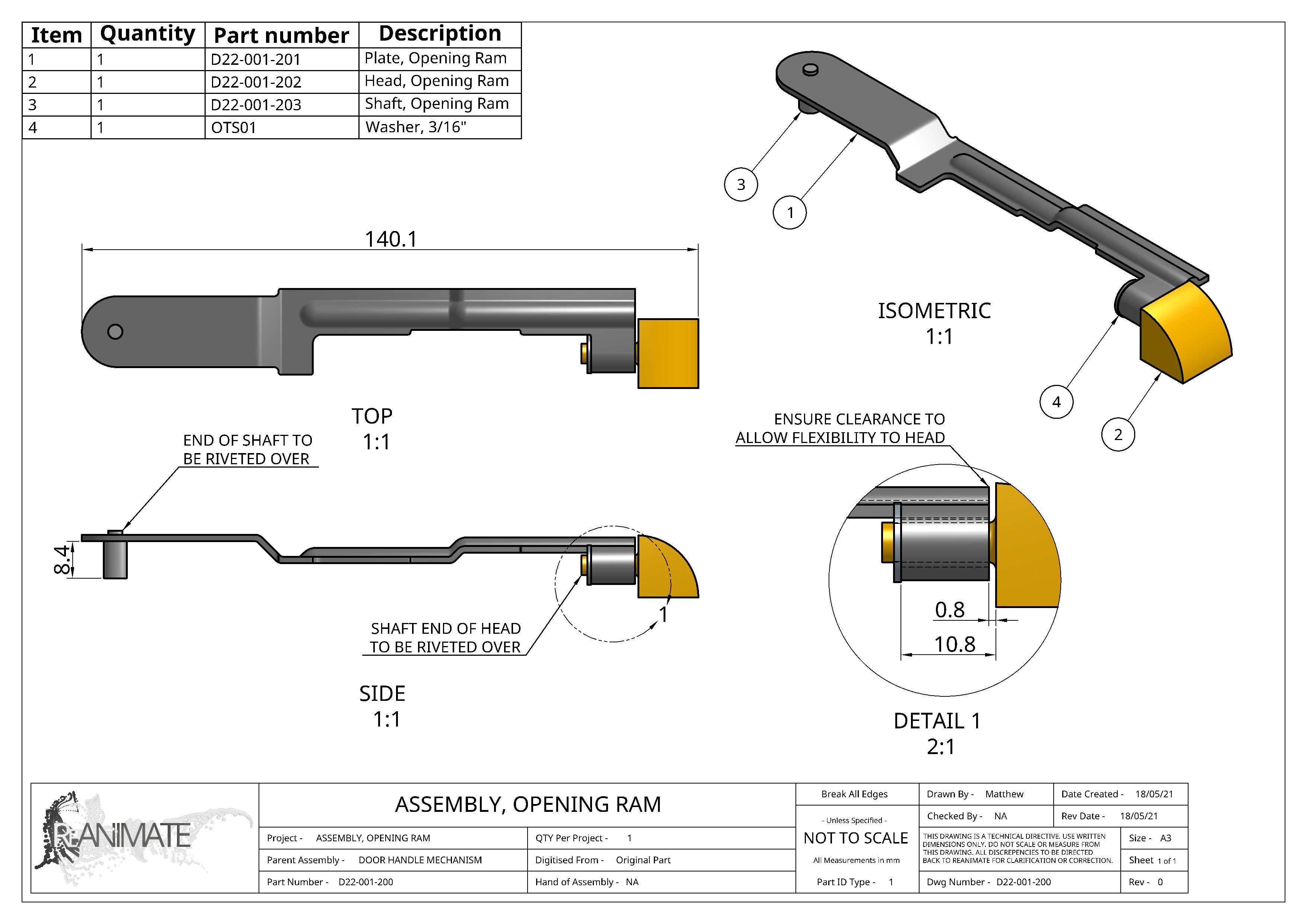
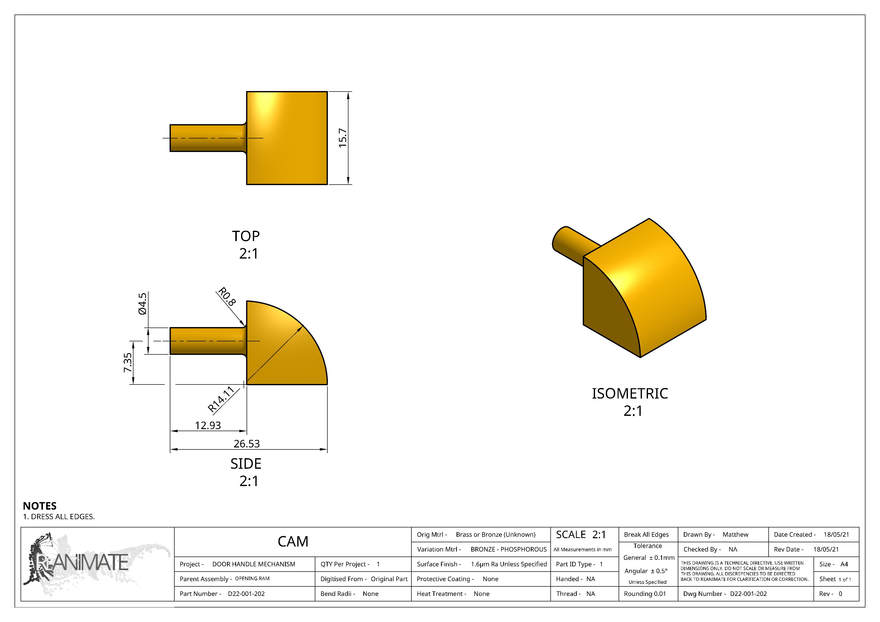
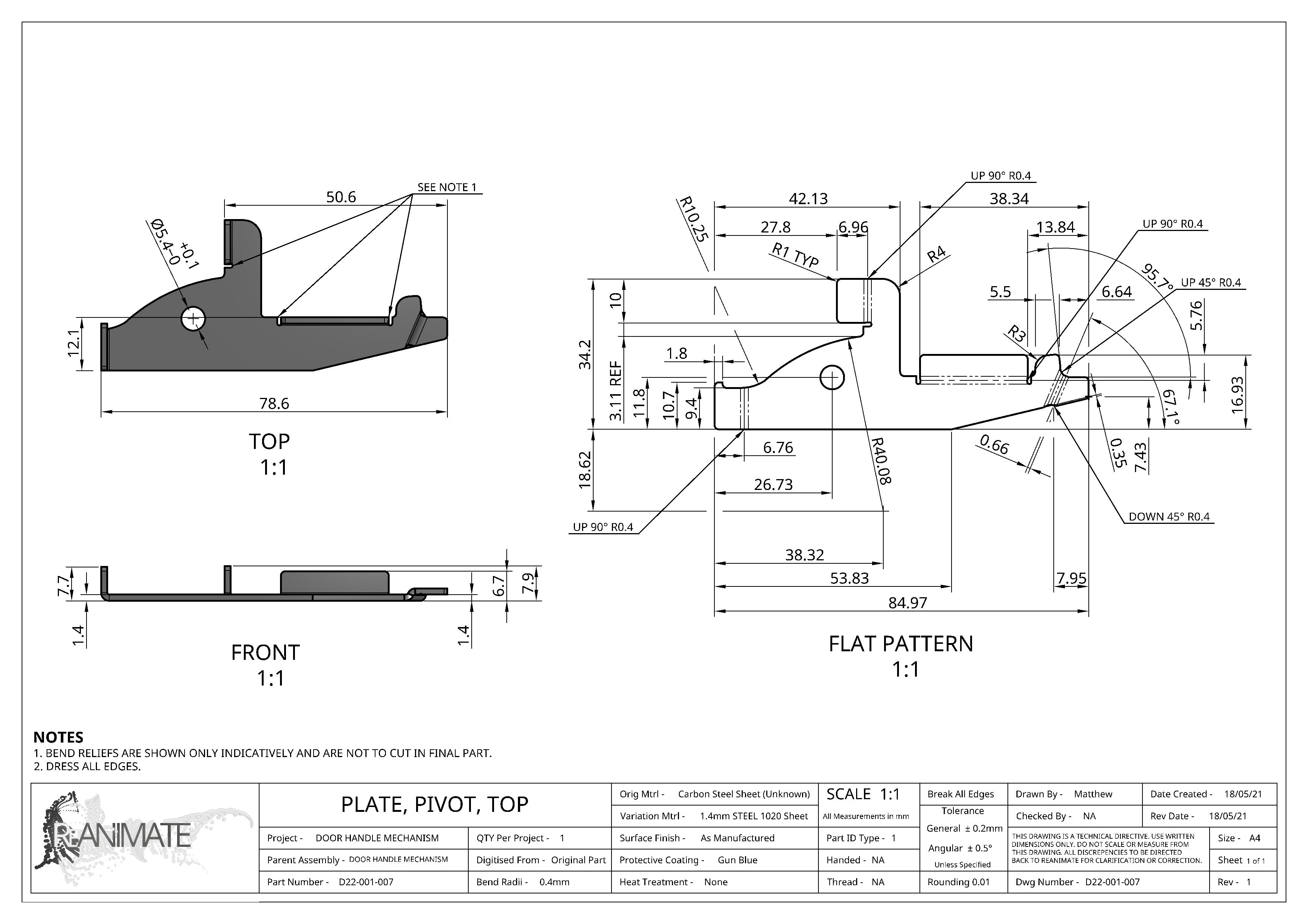
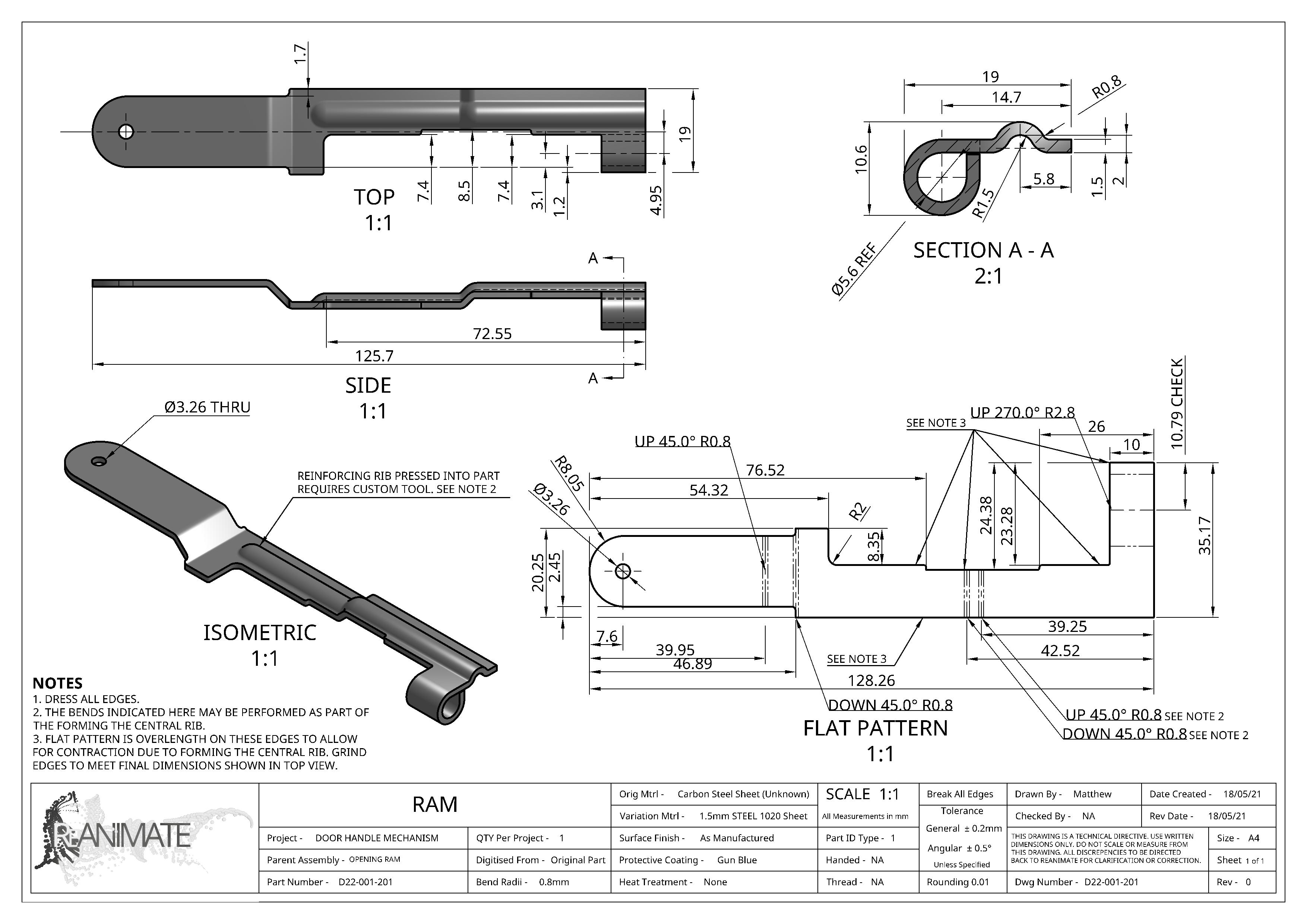
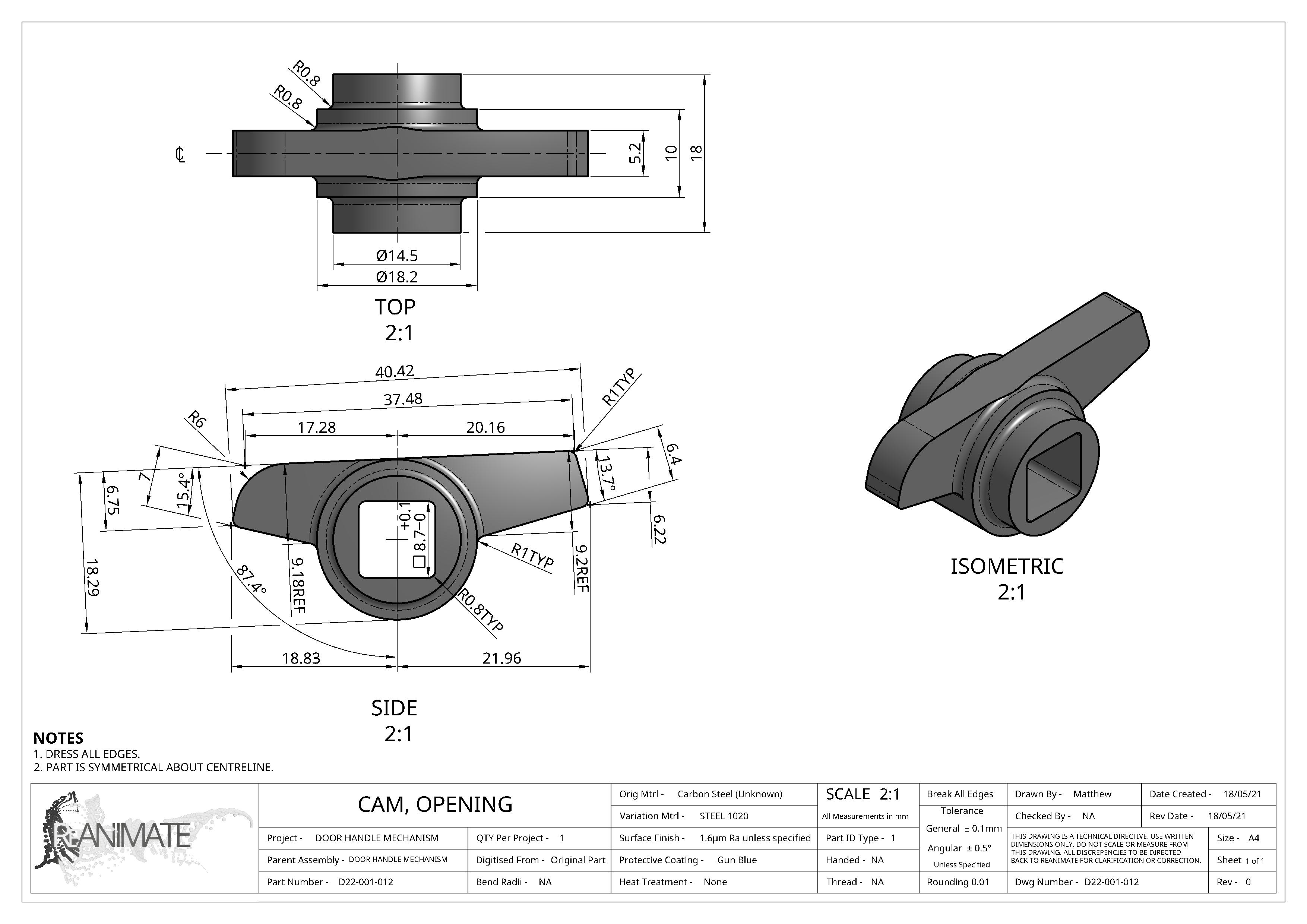
Sophisticated digital work practice (parametric sketching and constraining) helps to ‘self-check’ the part digitization, keeping the geometry extremely clean for 3D or 2D annotation in the deliverables, as well as enabling assembly-based checks such as clash and clearances. In addition, fabrication information can be produced such as sheet metal flat patterns, depending on the purpose of the digitization. The physical process is to use datum edges and triangulation where required, in order to remove running dimensional errors.
4. Collaboration and ‘out-sourcing’
As ReAnimate provides the service of documentation, collaboration will be sought to prepare and measure larger items or perform material assessments depending on the end use of the documentation. For working with heritage items, they may require additional laboratory study to determine finishes or compositions. For re-manufacture, additional engineering analysis and approval will need to be sought. ReAnimate will work with a network of companies and individuals to fill these gaps.
5. Digital and physical handback
When jobs are complete, it is time to hand data and objects back. Part of our process is to prepare for this point, which will include updates around cost progress or critical decision points. Once all items have been reasonably reviewed and closed out, handover can commence. Deliverables will typically be;
- The parts and assemblies themselves, in the state that was agreed to (disassembled, restored, assembled)
- Documentation data, which may be 2D drawings, 3D models or both, structured data, web links to fluid visualisation or storage as previously agreed to.
- A digital version of the job sheet, featuring processes outlined above, for traceability.
Conclusion
This post outlines the technology and process we employ for most reverse engineering projects. Get in touch if you would like to explore more or talk about options.
